Every year, our engineering team fields dozens of calls from clients whose distribution cabinets failed EMC certification at the last stage Test continuity 1. The culprit is almost always the same: a tiny gap around the cam lock that acts like a slot antenna 2, bleeding electromagnetic interference 3 into or out of the enclosure. It's a frustrating and costly problem, but one that is entirely preventable with the right hardware and the right assembly approach.
Conductive cam locks for distribution cabinets must provide continuous electrical contact with the enclosure door and frame, using low-resistance conductive gaskets and zinc-coated or chromate-treated metal surfaces to achieve RF attenuation levels between 20 dB and 120 dB, depending on enclosure class and applicable standards such as EN 60 529, MIL-STD-461, or VDE requirements.
Below, we break down the exact shielding specs, material choices, assembly methods, and international standards you need to know. Whether you build telecom racks, power distribution cabinets, or high-security military enclosures, this guide will help you select and install conductive cam locks with confidence.
How can I ensure my conductive cam lock selection meets strict EMC shielding requirements for my project?
When we first started shipping conductive cam locks to data center integrators in Europe, the feedback was clear: "good mechanical lock, but we need proof it holds the shielding line." That pushed our R&D team to rethink cam lock design from the ground up, treating shielding as a primary function rather than a secondary benefit.
To ensure your conductive cam lock meets EMC shielding requirements, select locks with integral conductive inserts, verify continuous metal-to-metal contact across the full door interface, and confirm the assembly achieves the target attenuation level—typically 20 dB for commercial or up to 120 dB for military-grade enclosures—across your project's relevant frequency range.

Why the Cam Lock Is a Weak Link
A distribution cabinet door is only as shielded as its worst gap. The cam lock penetration creates an aperture in the enclosure wall. If that aperture is not electrically sealed, it behaves like a slot antenna. The rule of thumb is the 1/20 wavelength rule 4: any slot longer than 1/20th of the interfering signal's wavelength will significantly degrade shielding. At 1 GHz, that critical slot length is just 15 mm. A standard cam lock cutout is typically 22 mm in diameter—already over the threshold.
Selecting the Right Lock Architecture
Not all cam locks are created equal for EMC duty. Here is what to look for:
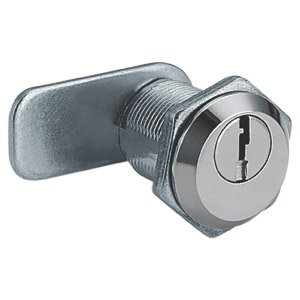
- Quarter-turn or double-bit cam locks with conductive inserts 5 that maintain a metal-to-metal path when locked.
- 130° or 180° cam rotation for tight door compression against conductive seals 6.
- Exchangeable double-bit inserts that allow field upgrades without replacing the entire lock body.
- Integrated conductive gasket groove around the lock barrel for a secondary seal.
Shielding Levels at a Glance
| Cabinet Shielding Level | Typical Attenuation | Common Applications | Cam Lock Requirement |
|---|---|---|---|
| Level 1 (Basic EMI) | 20–40 dB | Commercial IT racks, telecom | Zinc-plated steel lock, conductive gasket |
| Level 1+ (Enhanced) | 40–60 dB | Industrial automation, labs | Chromate-treated lock, dual-layer gasket |
| Level 2 (Faraday Cage) | >120 dB | Military, TEMPEST, hyperscale DC | Copper-bonded lock, welded conductive ring |
Our production line now offers three tiers of conductive cam locks mapped directly to these levels. For most commercial distribution cabinets, a Level 1 lock with a zinc-coated body and a self-adhesive EMC/IP gasket is sufficient. For higher demands, we provide chromate-treated aluminum bodies with spring-loaded conductive fingers around the barrel.
Pre-Testing Your Selection
Before committing to a full order, there is a simple pre-test method our engineers recommend. Apply copper tape around the cam lock cutout and measure shielding effectiveness 7 with a near-field probe. If the tape-sealed hole meets your target dB, a properly installed conductive cam lock with equivalent contact resistance will perform the same or better. This saves time and avoids expensive rework.
The key takeaway: shielding starts at specification. Define your target attenuation, frequency range, and IP rating before selecting a cam lock. Then confirm the lock's conductive path is unbroken from barrel to cam arm to door panel to frame.
What assembly techniques should I use to maintain electrical continuity between the cam lock and my cabinet door?
In our factory, we run continuity tests on every conductive cam lock assembly before it ships. Over 35 years, we have learned that even the best lock fails its EMC mission if installed incorrectly. The assembly stage is where shielding lives or dies.
To maintain electrical continuity, remove any non-conductive coatings from mating surfaces, use star washers or serrated flange nuts to bite into bare metal, apply conductive EMC gaskets around the lock barrel, and torque all fasteners to the manufacturer's specification to ensure consistent low-impedance contact over the product's lifespan.

Step-by-Step Assembly Guide
Here is the approach we recommend to our OEM partners:
- Prepare the cutout. Deburr the cam lock hole. If the door panel is powder-coated or painted, scrape or chemically strip the coating from the contact ring around the hole—at least 3 mm beyond the lock flange diameter.
- Apply the conductive gasket. Place a self-adhesive combined EMC/IP gasket onto the lock flange or directly onto the door panel's bare metal ring. This gasket provides both RF shielding and ingress protection (typically IP55 per EN 60 529 8).
- Insert the cam lock. Slide the lock barrel through the cutout. Ensure the gasket compresses evenly around the full circumference.
- Secure with conductive hardware. Verwenden Sie eine star washer 9 or serrated lock nut on the interior side. These fasteners cut through residual oxide layers and create metal-to-metal bonding.
- Torque to spec. Over-tightening crushes the gasket and reduces its lifespan. Under-tightening leaves gaps. Follow the lock manufacturer's torque value—our locks typically specify 2.5–3.5 Nm.
- Test continuity. Use a milliohm meter across the lock body, the door panel, and the cabinet frame. Target resistance should be below 2.5 mΩ for Level 1 enclosures and below 1 mΩ for Level 2.
Common Assembly Mistakes
| Mistake | EMC Consequence | Fix |
|---|---|---|
| Leaving paint or powder coat under the lock flange | High contact resistance; RF leakage | Strip coating from contact ring before installation |
| Using nylon washers or plastic spacers | Complete break in conductive path | Replace with star washers or conductive flat washers |
| Skipping the EMC gasket | Slot-antenna effect around barrel | Always install a conductive gasket rated for the target frequency |
| Uneven gasket compression | Partial shielding; intermittent leakage | Check gasket alignment and use calibrated torque wrench |
| Ignoring door hinge conductivity | Ground path interrupted at hinge | Use conductive hinge straps or bonding braids between door and frame |
Maintaining Continuity Over Time
Dynamic wear is a real concern. A cam lock on a distribution cabinet door may see thousands of open-close cycles over its service life. Each cycle stresses the conductive gasket and the contact surfaces. Our testing devices—we have over 35 in-house—simulate up to 50,000 cycles under load. The results show that zinc-nickel plated contacts hold lower resistance longer than plain zinc, and spring-energized gaskets outperform simple foam gaskets after 10,000 cycles.
We also recommend periodic re-torquing during scheduled maintenance windows, especially in environments with vibration (e.g., near generators or HVAC systems). A quick milliohm check every 12 months catches degradation before it causes certification issues.
Finally, cable shield termination matters too. If shielded cables enter the enclosure near the cam lock, their braids must bond directly to the cabinet's ground plane—not float or connect via pigtails. A pigtail connection at 500 MHz can add 20 dB of leakage compared to a 360° clamp termination.
How do I evaluate the conductivity and shielding effectiveness of different cam lock materials for my enclosures?
When we source raw materials for our cam lock production, conductivity and corrosion resistance sit at the top of every engineering review. We have tested everything from pure copper to conductive polymer composites. The results are clear: material choice shapes shielding performance more than almost any other variable.
Evaluate cam lock materials by comparing their electrical conductivity (measured in % IACS), corrosion resistance, magnetic permeability, density, and cost. Copper offers the highest conductivity (100% IACS) for superior RF reflection, while zinc-coated steel provides the best balance of shielding, durability, and cost for most industrial distribution cabinet applications.

Material Properties Compared
| Property | Copper | Zinc-Coated Steel | Chromated Aluminum | Conductive Plastic |
|---|---|---|---|---|
| Conductivity (% IACS) | 100% | 8–12% | 35–40% | <1% |
| Density (g/cm³) | 8.96 | 7.85 | 2.70 | 1.2–1.5 |
| Korrosionsbeständigkeit | Moderate (patina) | Good (with plating) | Excellent (chromate) | Excellent |
| Magnetic Permeability 10 | 1.0 (non-magnetic) | ~100–200 (ferromagnetic) | 1.0 (non-magnetic) | 1.0 |
| Relative Cost | Hoch | Low–Medium | Mittel | Niedrig |
| Best For | High-frequency E-field reflection | Broadband shielding, magnetic fields | Lightweight enclosures | Non-structural gaskets |
Understanding Reflection vs. Absorption
EMC shielding works through two primary mechanisms: reflection and absorption. High-conductivity materials like copper and aluminum excel at reflection, bouncing electromagnetic waves away from the enclosure surface. This is most effective against electric fields (E-fields) at high frequencies.
Steel, on the other hand, offers a dual advantage. Its moderate conductivity provides reflection, while its high magnetic permeability delivers strong absorption of magnetic fields (H-fields), especially at low frequencies below 1 MHz. This is why 2 mm galvanized steel remains the standard for cabinet walls in TEMPEST and EMPP applications where both E-field and H-field attenuation matter.
For the cam lock itself, the body is a small component relative to the enclosure wall. Its primary job is to not break the conductive chain. A zinc-nickel plated steel cam lock with a contact resistance below 2.5 mΩ will perform effectively in cabinets rated up to 60 dB. For cabinets targeting 100 dB or higher, copper-plated or solid brass locks are worth the premium.
The Gasket Factor
The gasket around the cam lock barrel is just as important as the lock body material. Modern hybrid gaskets combine a conductive elastomer core with an IP-rated outer seal. These achieve low contact resistance (often below 5 mΩ per linear centimeter) while providing IP65 or IP66 waterproofing.
There is a genuine tension between EMC and IP performance. A gasket optimized purely for conductivity may not compress evenly enough for water ingress protection. A gasket designed purely for IP66 may use non-conductive rubber. Our approach is to offer combined EMC/IP gaskets that meet both requirements simultaneously, tested to EN 60 529 for ingress protection and verified for RF attenuation on our in-house shielding effectiveness test bench.
Lightweight Alternatives and Their Limits
Conductive plastics have improved significantly. Some carbon-fiber-loaded polymers now achieve 5–10% IACS conductivity. They are attractive for weight-sensitive or cost-sensitive applications. However, they cannot match metals for shielding above 1 GHz, and they lack the mechanical strength required for cam lock bodies that endure thousands of actuation cycles. In our experience, conductive plastics work best for gasket carriers, cable gland inserts, and non-structural shielding components—not for the lock mechanism itself.
Which international EMC standards must my distribution cabinet hardware comply with to pass safety certification?
Our export team ships conductive cam locks to over 30 countries across North America and Europe. Each market has its own certification landscape. We have learned—sometimes the hard way—that a lock passing VDE testing in Germany does not automatically satisfy MIL-STD-461 requirements for a US defense contractor. Knowing which standards apply to your project is the first step toward certification success.
Distribution cabinet hardware must comply with standards including EN 55032 and EN 61000-6-2 for commercial EMC in Europe, FCC Part 15 in the US, MIL-STD-461 (requiring 80–100 dB attenuation) for military applications, and EN 60 529 for ingress protection, with VDE or TUV certification often required for high RF attenuation claims.

Key Standards Breakdown
Here is a practical overview of the standards most relevant to conductive cam locks in distribution cabinets:
EN 55032 / CISPR 32 — Limits for electromagnetic emissions from multimedia equipment. Relevant when the cabinet houses IT or telecom gear. Defines radiated and conducted emission limits.
EN 61000-6-2 — Generic immunity standard for industrial environments. Your enclosure must withstand external electromagnetic disturbances without degrading the equipment inside.
FCC Part 15 — US standard for unintentional radiators. Cabinets housing electronics that could emit RF energy must limit emissions below FCC thresholds.
MIL-STD-461G — US military standard requiring 80–100 dB of shielding effectiveness. Applies to defense and some government infrastructure. Demands rigorous testing across a wide frequency spectrum.
EN 60 529 (IP Ratings) — Defines ingress protection. While not strictly an EMC standard, IP55 or IP66 compliance is often bundled with EMC requirements because the same seals and gaskets serve both functions.
TEMPEST / SDIP-27 — NATO standard for information security shielding. Cabinets must prevent detectable electromagnetic emanations. Attenuation levels can exceed 100 dB for electric fields across 1 kHz to 10 GHz.
Regional Compliance Comparison
| Requirement | Europe (CE) | USA (FCC/MIL) | NATO (TEMPEST) |
|---|---|---|---|
| Emission Limits | EN 55032 | FCC Part 15 | SDIP-27 Level A/B/C |
| Immunity | EN 61000-6-2 | MIL-STD-461G RE/RS | SDIP-27 |
| Shielding Effectiveness | VDE-certified (varies) | 80–100 dB (MIL) | >100 dB E-field |
| IP Rating | EN 60 529 (IP55 typical) | NEMA 4X (equivalent) | Project-specific |
| Certification Body | TUV, VDE | UL, IAPMO | National security agencies |
| Cam Lock Impact | Must maintain conductive seal | Must meet enclosure SE spec | Welded/bonded lock assemblies |
Navigating the Standards Gap
There is a real debate in the industry about over-engineering versus practical compliance. Level 2 cabinets offering more than 120 dB of attenuation are essential for military facilities and certain government data centers. But for a commercial telecom rack, 20–40 dB of attenuation—achievable with standard conductive cam locks and gaskets—is typically sufficient and far more cost-effective.
Our UL, TUV, and IAPMO certifications cover the hardware quality and safety side. But shielding effectiveness certification applies to the complete enclosure assembly, not just the lock. This means your cam lock must be tested as part of the finished cabinet. We provide full technical datasheets with contact resistance values, gasket impedance curves, and frequency-dependent attenuation graphs so our clients' test labs can model the lock's contribution to overall enclosure shielding before building prototypes.
Practical Certification Tips
First, identify your target market and its primary standard (CE for Europe, FCC for the US, MIL-STD for defense). Second, define the shielding class your end customer requires. Third, request material certifications and test reports from your cam lock supplier. Our sales team at sales@hingelocks.com provides these documents as part of every quotation. Fourth, budget for enclosure-level testing at an accredited lab. The cam lock alone cannot be certified for EMC—it must perform within the system.
Finally, keep documentation current. Standards evolve. EN 55032 replaced EN 55022 in 2017. MIL-STD-461G replaced the F revision in 2015. Using outdated test reports can delay or derail certification.
Schlussfolgerung
Conductive cam locks are small components with outsized impact on your cabinet's EMC integrity. Choose the right material, assemble with continuous conductive paths, and match your hardware to the applicable international standards. If you need help selecting or customizing conductive cam locks for your project, reach out to our team at hingelocks.com—we are here to help you pass certification the first time.
Footnotes
- Explains what continuity is, why it's important, and how to perform a continuity test using a multimeter. ↩︎
- Provides a clear definition and explanation of slot antennas. ↩︎
- Authoritative source, clear definition of electromagnetic interference. ↩︎
- Explains how aperture size, including the 1/20 wavelength rule, affects EMI shielding effectiveness. ↩︎
- Discusses conductive elastomers used for EMI shielding, including their use in molded parts and gaskets. ↩︎
- Explains how EMI gaskets, which are conductive seals, prevent electromagnetic interference and provide environmental protection. ↩︎
- Defines EMI shielding effectiveness as the reduction in signal strength, measured in decibels. ↩︎
- Official IEC page explaining the IP code (Ingress Protection) as defined by IEC 60529. ↩︎
- Explains that star washers enhance grip, prevent loosening, and improve electrical conductivity, ideal for electrical grounding. ↩︎
- Defines magnetic permeability as the relative increase or decrease in the resultant magnetic field inside a material. ↩︎